Sectieoverzicht


    • In this unit you will learn that:

      • Circuit diagrams are used to show how electrical components are connected in a circuit
      • Individual circuit components are represented using circuit symbols
      • Current is the flow of electrons around a circuit
      • Ammeters are used to measure the current flowing through components
      • Components in a circuit resist current flow
      • Voltmeters are used to measure the potential difference across components

    • At the flick of a switch, turn of a knob or the push of a button, we have instant power. This is possible because of the electric current. Electric current has revolutionised modern-day living. From the time we wake up till the time we sleep at night, our life is dependent on electricity. From the basic bread toaster and baking oven to the commonly used television all require electric current to operate. The most common device, mobile phones, uses the electric current to charge the battery for operation. Besides playing a major part at home, electricity also plays an important role in industries, transportation, and communication. 


      Into the Ordinary. (2017). What is electricity? (Standard YouTube licence)


      Electric current

      When a lot of free electrons are all moving in the same direction, we call it an electric current. The amount of electric current refers to the number of electrons passing through an area per unit of time and is measured in amperes (usually called amps for short), abbreviated with a capital A. 

      Electric Current is the rate of flow of electrons in a conductor. 

      Flow of electrons

      When electric charges move in a wire, we say that an electric current flows in the wire. It's like the way a current of water flows in a river. It is important to note that current does not get used up in a circuit.  

      Batteries are often used as a source of electric current. A battery has a positive terminal, marked by a "+" symbol, and a negative terminal. The negative terminal has excess electrons, giving it a net negative charge. These electrons flow from the negative terminal to the positive terminal when there is a conductive path connecting them. 

      The direction of conventional current is opposite this, from the positive terminal to the negative terminal, as shown in Figure 1.

      Direction of electron flow

      Figure 1: When conductive material connects the two terminals of a battery, electrons will flow from the negative to the positive terminal. The conventional current will point from the positive to the negative terminal.

      Conventional Current Flow: The conventional current flow is from the positive to the negative terminal and indicates the direction in which positive charges would flow.

      Electron Flow: The electron flow is from negative to positive terminal. Electrons are negatively charged and are therefore attracted to the positive terminal as unlike charges attract.

      For an electric current to flow, we need two things:

      something to make the electricity flow, such as a battery or power pack

      a complete circuit for the current to flow in

      A circuit is made up of wires and components with a power source where current can flow, and the components will do work.

      A simple circuit is where a bulb is connected to a power source so the bulb can give off light. This is called a simple series circuit.

      A series circuit with 3 bulbs

      Figure 2: This is a simple series circuit with 3 bulbs. 

      Properties of the electric current

      We know that electric current is the result of the flow of electrons. The work done in moving the electron stream is known as electrical energy. Electrical energy can be converted into other forms of energy such as heat energy and light energy. For example, the electric energy in a bulb is converted into light energy, electrical energy in an iron is converted into thermal energy. 

      There are two types of electric current known as alternating current (AC) and direct current (DC). The direct current can flow only in one direction, whereas the alternating direction flows in two directions. Direct current is seldom used as an energy source. It is mostly used in low voltage applications such as charging batteries. 

      Alternating current is used to operate appliances for household, industrial and commercial use.

      The electric current is measured in ampere. One ampere of current represents one coulomb of electric charge moving past a specific point in one second.

      1 ampere = 1 coulomb / 1 second


      FuseSchool Global Education. (2020). Electricity current (Standard YouTube licence)


    • Current investigation

      1. Click on the link below:

      https://phet.colorado.edu/sims/html/circuit-construction-kit-ac-virtual-lab/latest/circuit-construction-kit-ac-virtual-lab_en.html

      2.  Using the components on the left-hand side of the screen build a series circuit with:

      1 battery

      1 bulb

      1 switch

      3 ammeters

      as shown in the picture below.

      screen shot of phet series circuit 

      What do you notice about the current readings on the ammeters?

      3. Copy this table into your notebook:

      Brightness

      1 cell

      2 cells

      3 cells

      1 bulb

      Normal


      2 bulbs


      3 bulbs


      4. Using the Phet simulation build the following circuits, noting the brightness of the bulbs in your table. (Each time you need to add a cell, add a battery)

      Whilst you are adding bulbs and batteries to your circuit, observe the speed of the animated electrons. 

      Series circuits practical 1

      What is the link between the brightness and the number of cells?  

      What is the link between the brightness and the number of bulbs?  

      Conclusion:

      With 1 battery and 1 bulb, 2 batteries and 2 bulbs, 3 batteries and 3 bulbs, the brightness of the bulb(s) is/are normal.  

      Adding cells/batteries to the circuit increases the brightness of the bulbs. This is because every time you add a battery, you give the current a bigger push to travel around the circuit. This causes an increase in the brightness.  

      When you add any component to a circuit, they resist the current - they slow the current down. This causes the bulbs to be dim.  

      The more components, the higher the resistance, the slower the current and the bulbs will be dim.

      The more batteries, the faster the current, the brighter the bulbs will be. 

    • Components

      A simple circuit comprises the power source, conductors, switch, and a resistor.

      Some of the more common components are:

      Circuit symbols

      The cell/battery is the power source. A battery is made up of 2 or more cells. The battery pushes the current around the circuit. The higher the power, the quicker the rate at which a battery can do work.

      Switch: It is a small gap in the circuit. There are several types of switches. A switch can be used to open or close a circuit i.e. it is used to turn a circuit on (closed) and off (open).

      Lamp: An electrical current heat the filament in a bulb so that it gives out light.

      Resistor: A resistor restricts or limits the flow of electrical current. A resistor has a resistance that does not change.

      Variable resistor: Adjusting this resistor changes its resistance. A variable resistor is used in some dimmer switches and volume controls.

      A motor spins round and a buzzer makes a buzzing sound. 

      Connecting wires are usually made from copper because copper is an excellent conductor of electricity. 

      An ammeter measures the current

      A voltmeter measures the potential difference in a circuit. 

      Electric circuits

      An electric current will not flow if we do not have a power source (a cell, battery or power pack). It also won't flow if the circuit is not complete. One end of the power source must be joined to the other end by the wires and components of the circuit.

      The simplest complete circuit is a piece of wire from one end of a battery to the other. An electric current can flow in the wire from one end of the battery to the other, but nothing useful happens. The wire just gets hot, and the battery goes flat.

      To do something useful with the electric current, we need to put an electrical component into the circuit, such as a lamp or motor that can use the current to make something happen.

      complete and incomplete circuits

      A switch is usually added to the circuit, so that the circuit can be broken, and the electric current will stopped when necessary.  

      Circuit diagrams

      The idea of a circuit diagram is to use circuit symbols instead of drawing each component in the circuit. Always try to make the wires straight lines, and don't be tempted to make them wiggly.

      The whole point is to make it easier to see what is connected to what. Here you can see how the symbols for a cell (not a battery!) and a lamp look in a circuit diagram.

      Circuit diagrams

      When you are drawing circuits, you MUST:

      1.     Use a sharp pencil and a ruler

      2.     Make sure your lines are straight and all angles are at 90°

      3.     Leave no gaps between wires and /or components


    • Series circuits

      In a television series, you get several episodes, one after the other. A series circuit is similar. You get several components one after the other.

      If you follow the circuit diagram from one side of the cell to the other, you should pass through all the different components, one after the other, without any branches.Simple series circuit

      If you put more lamps into a series circuit, the lamps will be dimmer than before.

      In a series circuit, if a lamp breaks or a component is disconnected, the circuit is broken/ incomplete, and all the components stop working.

      Series circuits are useful if you want a warning that one of the components in the circuit has failed. They also use less wiring than parallel circuits.

      Current in a series circuit

      Current is a measure of how much electric charge flows through a circuit. The more charge that flows, the bigger the current.

      Current is measured in units called amps. The symbol for amps is A. For example, 20A is a bigger current than 5A.

      A device called an ammeter is used to measure current. Some types of ammeter have a pointer on a dial, but most have a digital readout. To measure the current flowing through a component in a circuit, you must connect the ammeter in series with it.

      The current is the same everywhere in a series circuit. It does not matter where you put the ammeter, it will give you the same reading.


      All three ammeters give the same reading in this series circuit.

      Adding more cells

      The current in a series circuit depends upon the number of cells. The more cells you add, the greater the current.

      Series circuits with more cells

      The more cells, the greater the current.

      Current is not used up

      You might think that the current gets less as it flows through one component after another. But it is not like this. The current is not used up by the components in a circuit. This means that the current is the same everywhere in a series circuit, even if it has lots of lamps or other components.

      Series circuit with many components

      The current is the same everywhere in a series circuit.

      There are two types of circuits we can make, called series and parallel.

      The components in a circuit are joined by wires.

      if there are no branches then it's a series circuit

      if there are branches it's a parallel circuit

      Components in a circuit will resist current; components slow the current down. So the more components in a circuit, the slower the current will be.

      Parallel circuits

      In parallel circuits different components are connected on different branches of the wire. If you follow the circuit diagram from one side of the cell to the other, you can only pass through all the different components if you follow all the branches.

      A parallel circuit

      In a parallel circuit, if a lamp breaks or a component is disconnected from one parallel wire, the components on different branches keep working. And, unlike a series circuit, the lamps stay bright if you add more lamps in parallel.

      An incomplete parallel circuit

      Parallel circuits are useful if you want everything to work, even if one component has failed. This is why our homes are wired up with parallel circuits.

      Current in a parallel circuit

      The current in a parallel circuit splits into different branches then combines again before it goes back into the supply. When the current splits, the current in each branch after the split adds up to the same as the current just before the split.

      flow of current in a parallel circuit

      When the current splits along different branches, the proportion which travels along each branch is inversely proportional to the resistance one the branch. The higher the resistance on the branch, the less current will flow on that branch and visa versa. 

    • Investigating current in a series circuit


      Screenshot of Phet simulation of measuring current in a circuit.

      1. Copy the following table into your notebook:

      Number of batteries

      Number of bulbs

      Current (amps)

      1

      1


      1

      2


      1

      3


      3

      1


      3

      2


      3

      3


      2. Click on the link below: 
      https://phet.colorado.edu/sims/html/circuit-construction-kit-ac-virtual-lab/latest/circuit-construction-kit-ac-virtual-lab_en.html

      3. Using the Phet simulation, build the following circuits, noting the ammeter readings in your table.
      Series circuit practical measuring current
      What do you notice about the current in the circuits?
      How does changing the number of bulbs affect the current?
      How does changing the number of batteries affect the current?

      Conclusion:
      The first point to note is that in a series circuit, the ammeter reading on both ammeters will be the same. This is because the current only has one path to travel. At any point in a series circuit, the current will be the same.

      Increasing the number of bulbs in a circuit increases the resistance in a circuit and will slow the current down causing you to note a lower reading on each ammeter. 
      Increasing the batteries, has the effect of reducing the resistance, so the current will travel faster round the circuit causing you to note a higher reading on the ammeters. 

    • Investigating current in a parallel circuit


      1. Click on the link below:

      https://phet.colorado.edu/sims/html/circuit-construction-kit-ac-virtual-lab/latest/circuit-construction-kit-ac-virtual-lab_en.html

      2. Build a parallel circuit as shown in the picture below:

      Screenshot of a Phet simulation of a parallel circuit.

      2.  Close the switch. What do you notice about the brightness of the bulbs? Are they equally bright?

      What do you notice about the ammeter readings which are alongside each bulb?

      Are they the same?

      If you add them together, do they add up to the ammeter readings of the current entering and leaving the circuit?

      Hint: they should!

      Conclusion:

      If you add the ammeter readings on the two branches:

      2.70 + 2.70 = 5.40 A which is the same as the current entering and leaving the circuit. 

      Both bulbs are equally bright and have the same amount of current flowing through them. This is because they are resisting the current equally. 

      Screen shot of a parallel circuit

      3. Remove the bulb from the first branch of the circuit. Is the bulb on the second branch still lit? What do you notice about the ammeter reading next to the bulb?

      Screen shot of a parallel circuit

      4. Open the switch. Replace the bulb, and add another branch to the circuit, with 2 bulbs and an ammeter. 

      5. Close the switch. What do you notice about the brightness of the bulbs? Are they equally bright?

      What do you notice about the ammeter readings which are alongside each bulb?

      Are they the same?

      If you add them together, do they add up to the ammeter readings of the current entering and leaving the circuit?

      Hint: they should!   

      Conclusion: 

      If you add the 3 ammeters together from the picture below:

      2.70 +2.70 + 1.35 = 6.75 A, which is equal to the current entering and leaving the circuit.

      The brightness of the bulbs and the ammeter reading of the branch added are not the same is the other two branches. This is because there are two bulbs sharing the circuit, which increases the resistance and reduces the speed of the current. 

      Phet screenshot

    • A cell/battery pushes electrons around a circuit. It is a kind of electron pump. This electrical pressure is called electromotive force (e.m.f) and is measured in volts (V).  

      When a cell is connected to a series of bulbs, the e.m.f pushes electrons round the circuit. The energy to do this comes from the chemical energy in the battery. The electrons give up this energy to the thin wires inside the bulb, so they get hot and glow.  
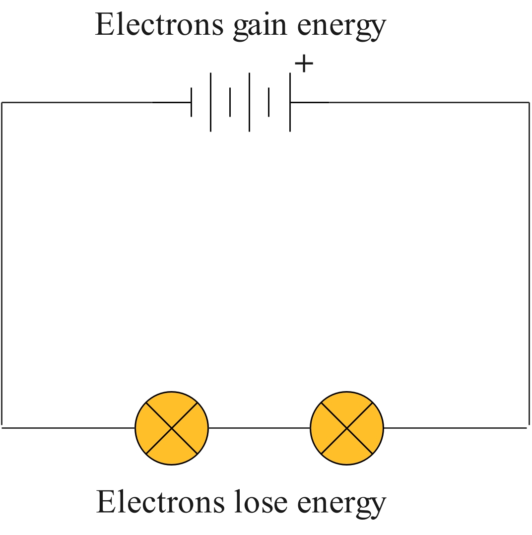
      emf

      Across each bulb, there is an electrical energy difference called potential difference or voltage. This is measured in volts using a voltmeter. 

      Current is the number of electrons that happen to be passing through any one point of a circuit at a given time. The higher the current, the more work it can do at the same voltage.

      Power = voltage x current. The higher the power, the quicker the rate at which a battery can do work—this relationship shows how voltage and current are both important for working out what a battery is suitable for.

      Voltage is measured in volts. The symbol for volts is V. For example, 230V is a bigger voltage than 12V. Voltage is measured using a voltmeter. Some types of voltmeters have a pointer on a dial, but most have a digital readout. To measure the voltage across a component in a circuit, you must connect the voltmeter in parallel with it.

      Activity 1:

      1. Click on the link below:

      https://phet.colorado.edu/sims/html/circuit-construction-kit-ac-virtual-lab/latest/circuit-construction-kit-ac-virtual-lab_en.html

      2. Build the circuit shown in the diagram below and measure the voltage of one of the lamps. series circuit with a voltmeter
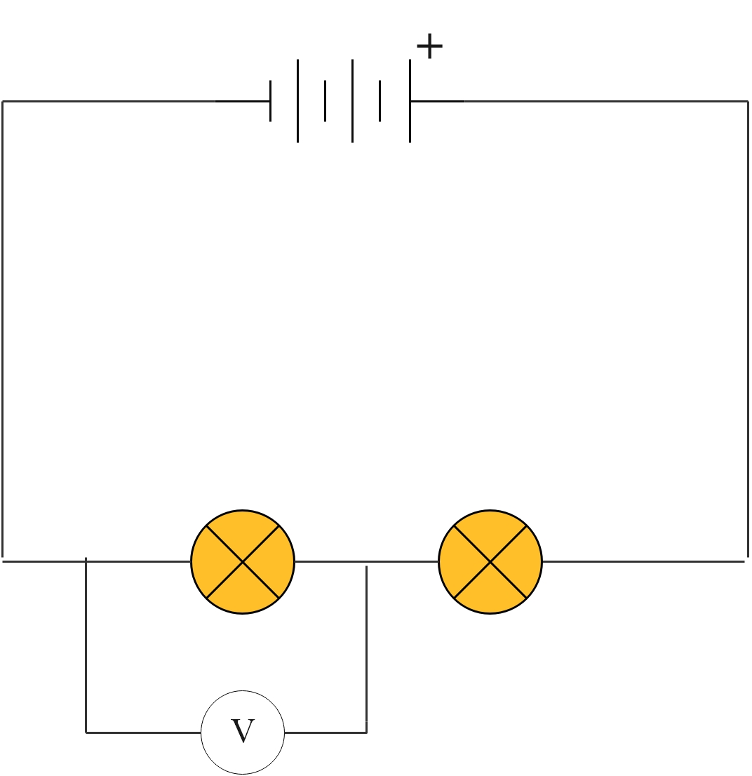
      What is the reading on the voltmeter?
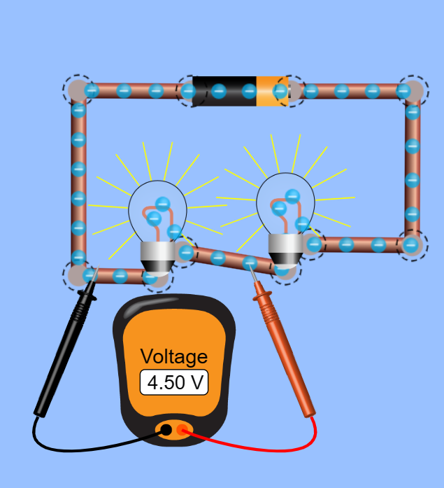
      phet screenshot voltage 1

      3. Move the voltmeter to the other lamp and measure the voltage through that lamp. 
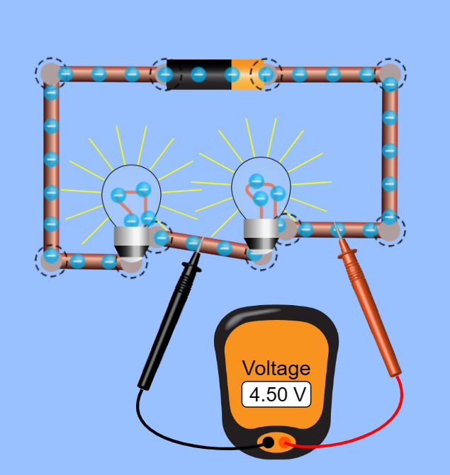
      phet screenshot voltage 2

      The total voltage across the lamps equals the voltage across the cell. 
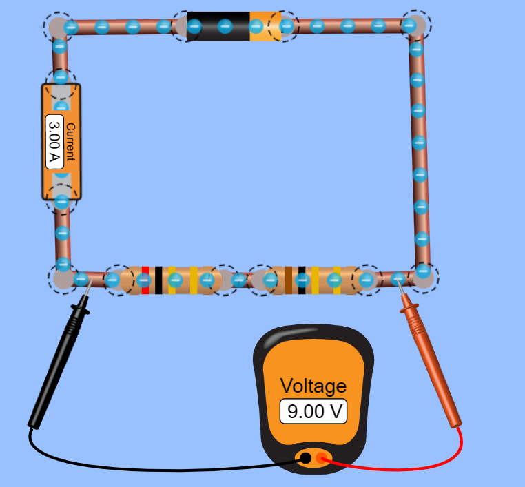
      phet screenshot resistor voltage 3


      Ohm's Law

      As previously mentioned, adding components to a circuit will resist the current, and are therefore called resistors. Resistors try to stop the current from flowing. Every material around the world has resistance for electric current.

      Some materials have small resistance, called conductors, whilst other materials have very high resistance, called insulators. 

      Ohms law states that the current flowing through a metal wire is proportional to the potential difference across it, providing the temperature remains constant. 

      So, if you double the potential difference, the current is doubled.  

      The thin wire in a bulb will resist the movement of electrons in it. The greater the resistance, the more voltage is needed to push a current through the wire. 
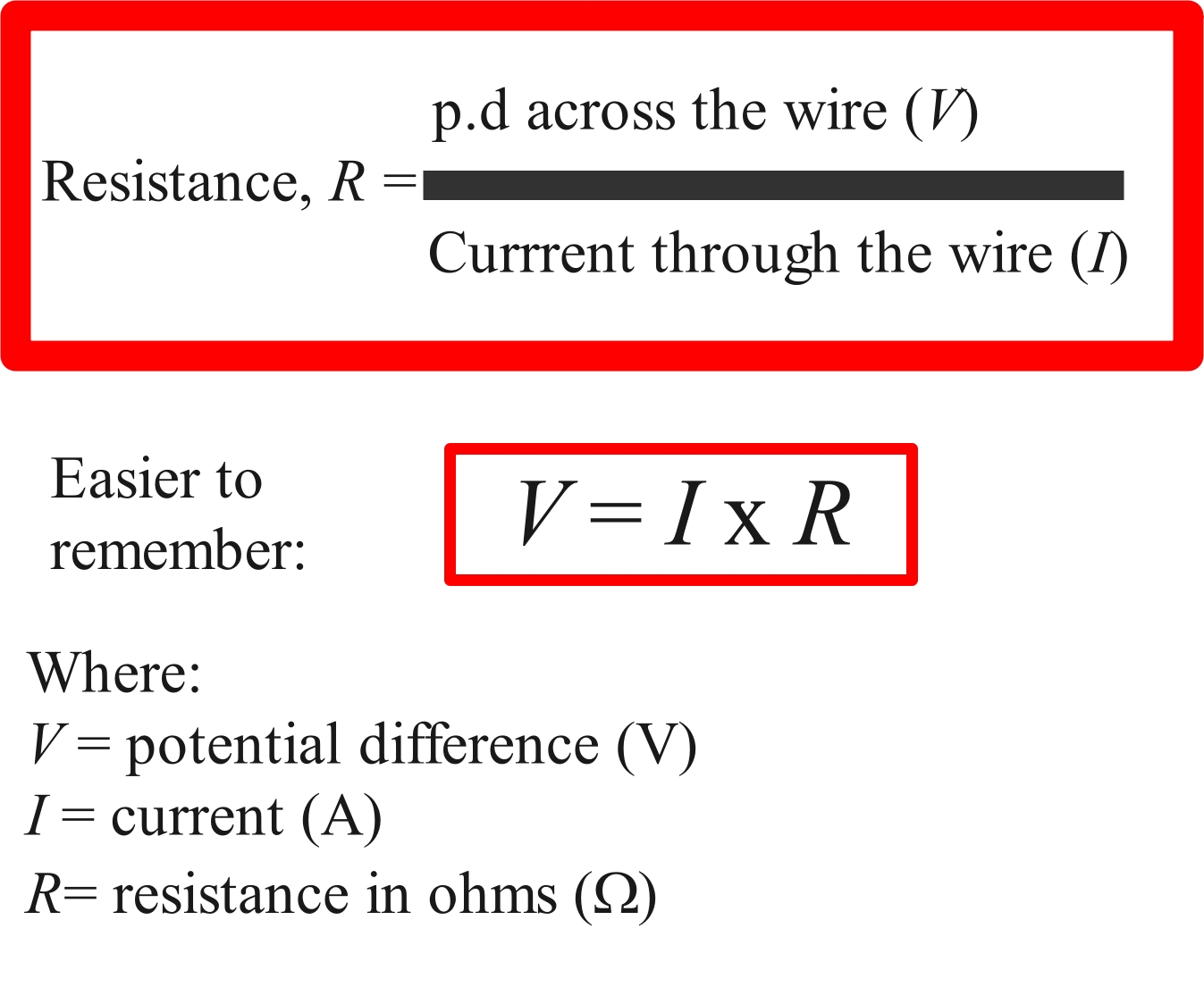
      ohms law

      A current of 3 A flows through a 240 V lamp. What is the resistance of the lamp?

      Resistance = 240 ÷ 3 = 80 Ω

      A 2 V battery is connected to a wire with a resistance of 20 Ω.  What current flows through the circuit? 
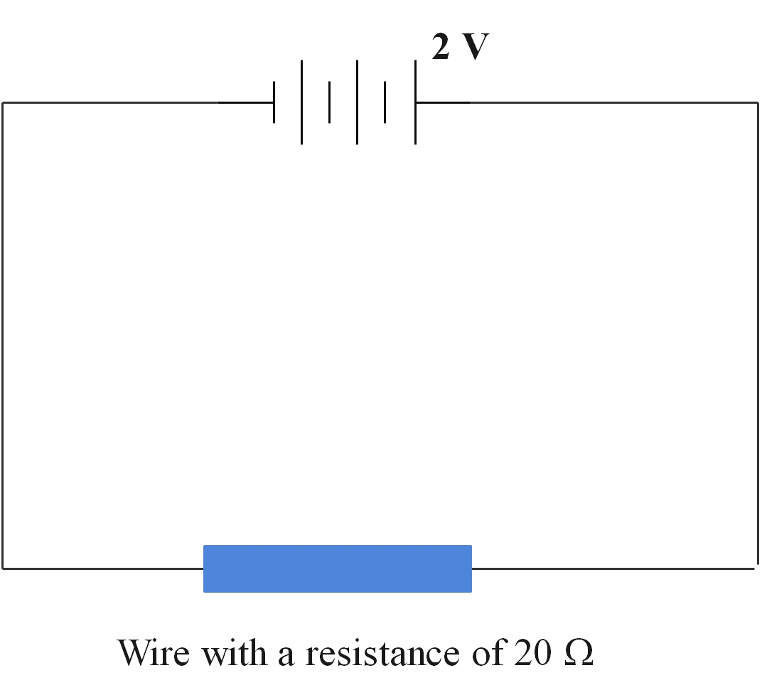
      wire resistance

      V = I x R

      2 = I x 20

      The current = 2/20 = 1/10 = 0.1 A

      Resistors are used in a circuit to reduce the current. A variable resistor or rheostat is used to vary the current in a circuit. The volume control on a radio is a rheostat as is a dimmer switch on lights.

      Activity 2

      1. Click on the link below:

      https://phet.colorado.edu/sims/html/ohms-law/latest/ohms-law_en.html

      2. Using the sliders on the right-hand side, reduce and increase the voltage and observe what happens to the current and the resistance. 

      You should see that as you reduce the voltage, the current decreases. As you increase the voltage, the current increases. This makes sense because the e.m.f is what pushes the current around the circuit. 

      3. Reset the circuit. Using the slider on the right, decrease and increase the resistance and observe the effect on both the voltage and current. 

      As you decrease the resistance, the current increases. As you increase the resistance the current decreases.  Any increase in resistance will slow down the current and visa versa.  

      Measuring resistance

      Activity 3

      1. Click on the link below:

      https://phet.colorado.edu/sims/html/circuit-construction-kit-ac-virtual-lab/latest/circuit-construction-kit-ac-virtual-lab_en.html

      2. Build the following circuit:
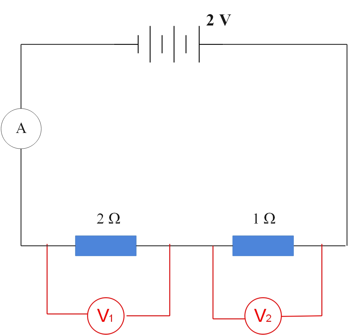
      Resistors in series

      3. Tap on the resistors and set one as 2 ohms, and the second as 1 ohm. Place a voltmeter over the 2 Ω resistor and note the voltage.
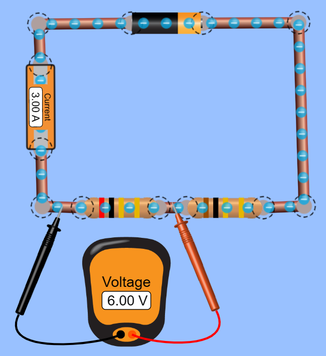
      phet screenshot resistor voltage 1

      4. Place the voltmeter over the 1 Ω resistor and note the voltage.
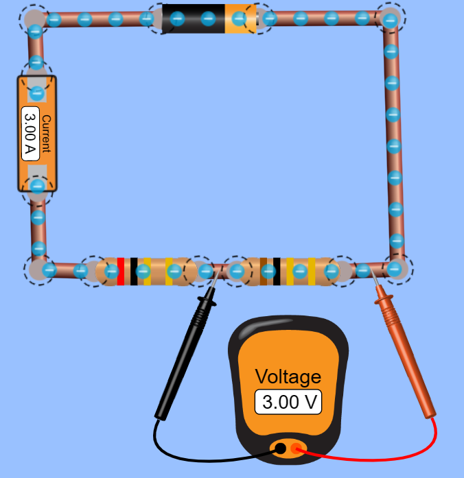
      phet screenshot resistor voltage 2

      5. Place the voltmeter across both resistors and note the voltage.  
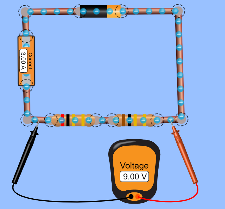
      phet screenshot resistor voltage 3

      The total potential difference is the sum of the potential difference across the separate resistors.  

      V3= V1 + V2  

      For the above circuit, the total potential difference is 9 V.

      The total resistance of a series circuit is equal to the sum of the separate resistance:

      R = R1 + R2

      So the resistance for the above circuit is:

      2 + 1 = 3 Ω

    • The following resources were consulted in the making of this study unit:

      • Wikipedia. (Last updated 2023). Electronic circuits. Available online here. (CC BY-SA)
      • LibreTexts. University of Wisconsin-Madison. Martin, H. (2020). Electric circuits. Available online here. (CC BY-SA)
      • LibreTexts. Crowell, B. (2020). Circuits. Available online here. (Not declared licence)
      • PhET Interactive Simulations. (nd). Circuit construction. Available online here (CC BY)
      • PhET Interactive Simulations. (nd). Ohm's Law. Available online here. (CC BY)
      • Harrage, E. (2023). All images. (CC BY)